




S-S4100 Single-Frequency Anti-jamming &Anti-spoofing Antenna
S-S4100 Single-Frequency Anti-jamming &Anti-spoofing AntennaSerialNumberprojectindex1Number of array elements4 Array Elements2size100× 100×24.9mm (±0.5mm)3weight≤310g4frequencyB1/E1/L15Anti-interference performance≥115dB (single jamming)≥100dB (three jamming )6Power supply voltageDC 12~36V7interface1xJ30J-9ZK , 1xSMA8Power consumption≤10W9Structural installation accessories8 M3 ×8 screws and 4 hax studsApplication Parameter Confirmation FormSerialNumbcontentdefault valuer1Structural installationStructural installation method:1.Overhead installationUse hex studs to mount the antennabody to the platform, ensuring aminimum clearance of 10 mm beneath the antenna for proper airflow and heat dissipation.2. Fact to face installationMount the antenna with its bottomsurface in close contact with a metal mounting surface for effective heat conduction.Default: Overhead installation.If overhead installation cannot beachieved, please inform us in advance so that we can discuss and determine an alternative solution.2connect1.Confirm whether a digital or radio frequency (RF) connection is used;2.Confirm the power supply method and power supply capacity;3.If using a digital connection, confirm the serial port output level;4.Confirm the output level of the anti- interference serial port5.Confirm the power supply connection method;6.Confirm the serial port connection method.1. Both connection methods aresupported, and the customer must confirm and select. Differentconnection methods correspond to different parameter configurations.2. Power supply method and capacity: The default power supply uses anXT30U-M male connector, and the power supply capacity must meet the device's peak power consumption of 15W.3. For digital connections, the default receiver serial port output level isLVTTL_3.3V. S232 is available as options.4. The default anti-interference serial port output level is LVTTL_3.3V.RS232 is available as an option.5. A J30J connection cable isprovided by default, and the power supply uses an XT30U-M maleconnector. The customer needs to provide the corresponding female connector for mating.6. A J30J connection cable isprovided by default, and the serial port uses a DuPont male pin connector.3Output Protocol (Receiver)If using a digital connection, please confirm the following built-in receiver configurations:1. Output protocol: UBX or NMEA0183;2. Baud rate: 115200 or 230400 or other;3. Output frequency: 5Hz.d dThe default built-in receiver configuration is as follows:1. Output protocol: UBX protocol;2. Baud rate: 115200;3. Output frequency: 5Hz.4Output Protocol (anti-jamming )Interference Monitoring Configuration: Output Protocol: ZSAJ ProtocolBaud Rate: 115200, 230400, or other (customizable upon request)Default configuration:Output Protocol: ZSAJ ProtocolBaud Rate: 1152005End useThe product is limited to civilian unmanned platforms and high-precision positioning scenarios, including but not limited to drones, unmanned ships, autonomous vehicles, marine operations, and surveying and mapping.6Application PlatformMulti-rotor drones, fixed-wing drones, unmanned surface vessels, autonomous vehicles, ground base stations, etc.7Main application scenariosAerial surveying, inspection and patrol, logistics and distribution, precisionagriculture, offshore operations, communication relay, scientific research, etc.8End-usecountry/region:Important Note: The above confirmation is the basis for product delivery. Once confirmed, any subsequent changes date. If the default configuration cannot meet your application requirements, please provide detailed specifications only permitted after mutual communication and confirmation. Unless otherwise specified, electrical connection acc the default configuration.Confirmation signature:Confirmation DateConfirmation FormCustomer confirmation□ Accept Default □ Customize: ______□ Digital Connection□ RF ConnectionPower Supply: ___________Power Supply Capacity: □ Meets SerialReceiver serial Port Level:□ Accepts Default□ Customizes: ____________Anti-interference serial Port Level:□ Accepts Default□ Customizes: ____________Power Connection: ___________Serial Port Connection: ___________□ Accept Default□ Customize: ______□ Accept Default□ Customize: ______End use: ______Application platform: ______Application scenario: ______Country and region: ______s may incur additional costs or affect the deliverys in the "Customization" section. mplementation iscessories (connectors, cables, etc.) will be based on
Category:
Key Words:
- Product Detail
- parameter
-
S-S4100 Single-Frequency Anti-jamming &Anti-spoofing Antenna
Serial
Numb
er
project index 1 Number of array elements 4 Array Elements 2 size 100× 100×24.9mm (±0.5mm) 3 weight ≤310g 4 frequency B1/E1/L1 5 Anti-interference performance ≥115dB (single jamming)
≥100dB (three jamming )
6 Power supply voltage DC 12~36V 7 interface 1xJ30J-9ZK , 1xSMA 8 Power consumption ≤10W 9 Structural installation accessories 8 M3 ×8 screws and 4 hax studs Application Parameter Confirmation Form
Serial
Numb
content default value r
1
Structural installation Structural installation method:
1.Overhead installation
Use hex studs to mount the antenna
body to the platform, ensuring a
minimum clearance of 10 mm beneath the antenna for proper airflow and heat dissipation.
2. Fact to face installation
Mount the antenna with its bottom
surface in close contact with a metal mounting surface for effective heat conduction.
Default: Overhead installation.
If overhead installation cannot be
achieved, please inform us in advance so that we can discuss and determine an alternative solution.
2 connect 1.Confirm whether a digital or radio frequency (RF) connection is used;
2.Confirm the power supply method and power supply capacity;
3.If using a digital connection, confirm the serial port output level;
4.Confirm the output level of the anti- interference serial port
5.Confirm the power supply connection method;
6.Confirm the serial port connection method.
1. Both connection methods are
supported, and the customer must confirm and select. Different
connection methods correspond to different parameter configurations.
2. Power supply method and capacity: The default power supply uses an
XT30U-M male connector, and the power supply capacity must meet the device's peak power consumption of 15W.
3. For digital connections, the default receiver serial port output level is
LVTTL_3.3V. S232 is available as options.
4. The default anti-interference serial port output level is LVTTL_3.3V.
RS232 is available as an option.
5. A J30J connection cable is
provided by default, and the power supply uses an XT30U-M male
connector. The customer needs to provide the corresponding female connector for mating.
6. A J30J connection cable is
provided by default, and the serial port uses a DuPont male pin connector.
3 Output Protocol (Receiver) If using a digital connection, please confirm the following built-in receiver configurations:
1. Output protocol: UBX or NMEA0183;
2. Baud rate: 115200 or 230400 or other;
3. Output frequency: 5Hz.
d d
The default built-in receiver configuration is as follows:
1. Output protocol: UBX protocol;
2. Baud rate: 115200;
3. Output frequency: 5Hz.
4 Output Protocol (anti-jamming ) Interference Monitoring Configuration: Output Protocol: ZSAJ Protocol
Baud Rate: 115200, 230400, or other (customizable upon request)
Default configuration:
Output Protocol: ZSAJ Protocol
Baud Rate: 115200
5 End use The product is limited to civilian unmanned platforms and high-precision positioning scenarios, including but not limited to drones, unmanned ships, autonomous vehicles, marine operations, and surveying and mapping. 6 Application Platform Multi-rotor drones, fixed-wing drones, unmanned surface vessels, autonomous vehicles, ground base stations, etc. 7 Main application scenarios Aerial surveying, inspection and patrol, logistics and distribution, precision
agriculture, offshore operations, communication relay, scientific research, etc.
8 End-use
country/region:
-
-
Anti interference Module
- Elements
- Bands
-
Applications
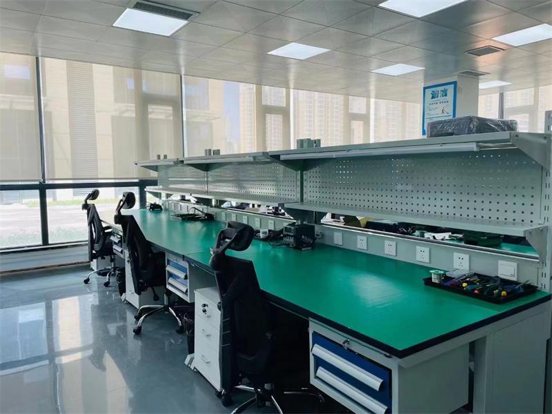
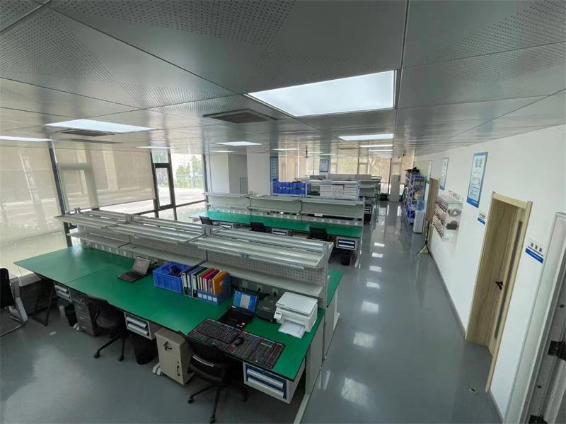
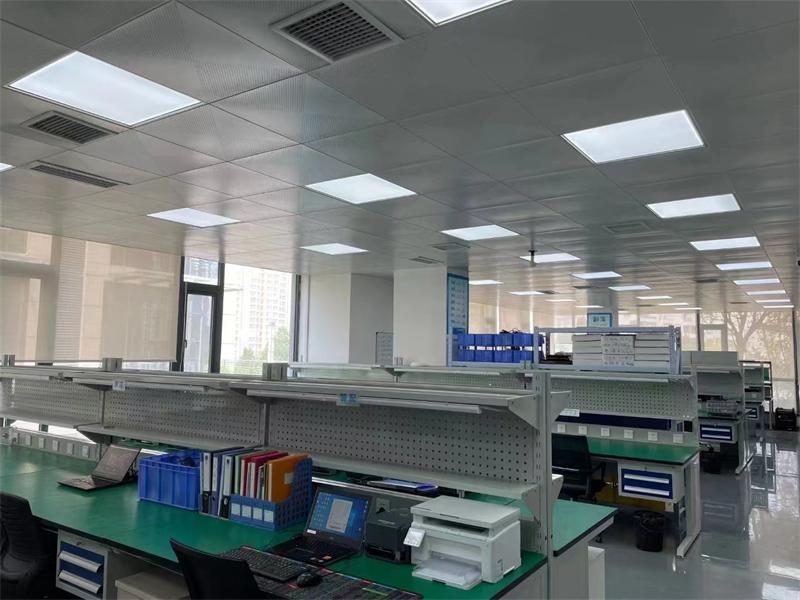
Factory Environment
Cinofiber will continue to be a leader in the optical communication industry, providing customers around the world with more stable, reliable, and high-quality products and services.

Questions And Answers
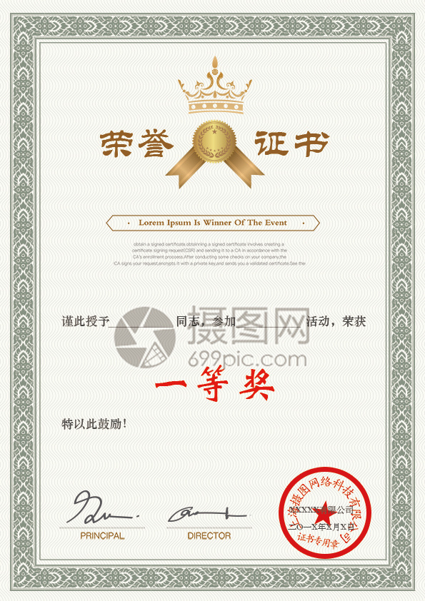
Certificate Of Honor




CONTACT
Service Hotline
ADD: Collaborative Innovation Park, Hengli Town, Dongguan City, Guangdong, China

Swarm Technology
Ensure your low altitude security!


Powered by:CEglobal