

图片名称

Drone Detection, Countermeasure, And Anti-interference Solution

全部
  • 全部
  • 产品管理
  • 新闻资讯
  • 企业视频
  • 企业图册
S-S8180 Single-Frequency Anti-jamming &Anti-spoofing Antenna
ZSAJ-S8180-01.png
ZSAJ-S8180-02.jpg
ZSAJ-S8180-07.jpg
ZSAJ-S8180-09.jpg

S-S8180 Single-Frequency Anti-jamming &Anti-spoofing Antenna

S-S8180 Single-Frequency Anti-jamming &Anti-spoofing Antenna Confirmation FormSerialNumberprojectindex1Number of array elements8-lement2size180×180×25.5mm (±0.5mm)3weight≤890g4frequencyB1/E1/L15Anti-interference performance≥115dB (single jamming)≥105dB (three jamming )≥90dB (seven jamming )6Power supply voltageDC 12~36V7interface1x J30J-9ZK, 1xSMA8Power consumption≤17W9Structural installation accessories16 M3×8 screws and 4 mounting bracketsApplication Parameter Confirmation FormSerialcontentdefault valueCustomer confirmationN b1Structural installationStructural installation method1)Overhead installationThe antenna body shall be mounted to the platform using the provided mounting brackets. A minimum clearance of 10mm shall be maintained beneath theantenna to ensure adequate airflow and heat dissipation.2) Face to face installationThe antenna shall be mounted with itsbottom surface in direct and full contact with a metal surface to maximize thermal conduction and heat dissipation.Default: Overhead installation.If overhead installation cannot beachieved, please inform us in advance so that we can discuss and determine an alternative solution.□ Accept Default □ Customize: ______2connect1. Confirm whether a digital or radio frequency (RF) connection is used;2. Confirm the power supply method and power supply capacity;3. If using a digital connection, confirm the serial port output level;4.Confirm the output level of the anti- interference serial port5.Confirm the power supply connection method;6.Confirm the serial port connection method.1. Both connection methods aresupported, and the customer must confirm and select. Differentconnection methods correspond to different parameter configurations.2. Power supply method and capacity: The default power supply uses anXT30U-M male connector, and the power supply capacity must meet the device's peak power consumption of 26W.3. For digital connections, the default receiver serial port output level isLVTTL_3.3V. RS232 is available as options.4. The default anti-interference serial port output level is LVTTL_3.3V.RS232 is available as an option.5. A J30J connection cable isprovided by default, and the power supply uses an XT30U-M maleconnector. The customer needs to provide the corresponding female connector for mating.6. A J30J connection cable isprovided by default, and the serial port uses a DuPont male pin connector.□ Digital Connection□ RF ConnectionPower Supply: __________Power Supply Capacity: □ Meets SerialReceiver serial Port Level:□ Accepts Default□ Customizes: ___________Anti-interference serial Port Level:□ Accepts Default□ Customizes: ___________Power Connection: __________Serial Port Connection: __________3Output ProtocolIf using a digital connection, please confirm the following built-in receiver configurations:1. Output protocol: UBX or NMEA0183;2. Baud rate: 115200 or 230400 or other;3. Output frequency: 5Hz.d dThe default built-in receiverconfiguration for the single-frequency anti-jamming antenna is as follows:1. Output protocol: UBX protocol;2. Baud rate: 115200;3. Output frequency: 5Hz.□ Accept Default □ Customize: ______4Output Protocol(anti-jamming )Interference Monitoring Configuration: Output Protocol: ZSAJ ProtocolBaud Rate: 115200, 230400, or other (customizable upon request)Default configuration:Output Protocol: ZSAJ ProtocolBaud Rate: 115200□ Accept Default□ Customize: ______5End useThe product is limited to civilian unmanned platforms and high-precision positioning scenarios, including but not limited to drones, unmanned ships, autonomous vehicles, marine operations, and surveying and mapping.End use: ______6Application PlatformMulti-rotor drones, fixed-wing drones, unmanned surface vessels, autonomous vehicles, ground base stations, etc.Application platform: ______7Main applicationscenariosAerial surveying, inspection and patrol, logistics and distribution, precisionagriculture, offshore operations, communication relay, scientific research, etc.Application scenario: ______8End-usecountry/region:Country and region: ______Important Note: The above confirmation is the basis for product delivery. Once confirmed, any subsequent changes may incur additional costs or affect the deliverydate. If the default configuration cannot meet your application requirements, please provide detailed specifications in the "Customization" section. mplementation is only permitted after mutual communication and confirmation. Unless otherwise specified, electrical connection accessories (connectors, cables, etc.) will be based on the default configuration.Confirmation signature:Confirmation Date

Key Words:

  • Product Detail
  • parameter
  • S-S8180 Single-Frequency Anti-jamming &Anti-spoofing Antenna Confirmation Form

    Serial

    Numb

    er

    projectindex
       
    1Number of array elements8-lement
    2size180×180×25.5mm (±0.5mm)
    3weight≤890g
    4frequencyB1/E1/L1
    5Anti-interference performance

    ≥115dB (single jamming)

    ≥105dB (three jamming )

    ≥90dB (seven jamming )

    6Power supply voltageDC 12~36V
    7interface1x J30J-9ZK, 1xSMA
    8Power consumption≤17W
    9Structural installation accessories16 M3×8 screws and 4 mounting brackets

    Application Parameter Confirmation Form

    Serialcontentdefault valueCustomer confirmation

    N b

    1

    Structural installation

    Structural installation method

    1)Overhead installation

    The antenna body shall be mounted to the platform using the provided mounting brackets. A minimum clearance of 10

    mm shall be maintained beneath the

    antenna to ensure adequate airflow and heat dissipation.

    2) Face to face installation

    The antenna shall be mounted with its

    bottom surface in direct and full contact with a metal surface to maximize thermal conduction and heat dissipation.

    Default: Overhead installation.

    If overhead installation cannot be

    achieved, please inform us in advance so that we can discuss and determine an alternative solution.

    □ Accept Default □ Customize: ______
    2connect

    1. Confirm whether a digital or radio frequency (RF) connection is used;

    2. Confirm the power supply method and power supply capacity;

    3. If using a digital connection, confirm the serial port output level;

    4.Confirm the output level of the anti- interference serial port

    5.Confirm the power supply connection method;

    6.Confirm the serial port connection method.

    1. Both connection methods are

    supported, and the customer must confirm and select. Different

    connection methods correspond to different parameter configurations.

    2. Power supply method and capacity: The default power supply uses an

    XT30U-M male connector, and the power supply capacity must meet the device's peak power consumption of 26W.

    3. For digital connections, the default receiver serial port output level is

    LVTTL_3.3V. RS232 is available as options.

    4. The default anti-interference serial port output level is LVTTL_3.3V.

    RS232 is available as an option.

    5. A J30J connection cable is

    provided by default, and the power supply uses an XT30U-M male

    connector. The customer needs to provide the corresponding female connector for mating.

    6. A J30J connection cable is

    provided by default, and the serial port uses a DuPont male pin connector.

    □ Digital Connection

    □ RF Connection

    Power Supply: __________

    Power Supply Capacity: □ Meets Serial

    Receiver serial Port Level:

    □ Accepts Default

    □ Customizes: ___________

    Anti-interference serial Port Level:

    □ Accepts Default

    □ Customizes: ___________

    Power Connection: __________

    Serial Port Connection: __________

    3Output Protocol

    If using a digital connection, please confirm the following built-in receiver configurations:

    1. Output protocol: UBX or NMEA0183;

    2. Baud rate: 115200 or 230400 or other;

    3. Output frequency: 5Hz.

    d d

    The default built-in receiver

    configuration for the single-frequency anti-jamming antenna is as follows:

    1. Output protocol: UBX protocol;

    2. Baud rate: 115200;

    3. Output frequency: 5Hz.

    □ Accept Default □ Customize: ______
    4

    Output Protocol

    (anti-jamming )

    Interference Monitoring Configuration: Output Protocol: ZSAJ Protocol

    Baud Rate: 115200, 230400, or other (customizable upon request)

    Default configuration:

    Output Protocol: ZSAJ Protocol

    Baud Rate: 115200

    □ Accept Default

    □ Customize: ______

    5End useThe product is limited to civilian unmanned platforms and high-precision positioning scenarios, including but not limited to drones, unmanned ships, autonomous vehicles, marine operations, and surveying and mapping.End use: ______
    6Application PlatformMulti-rotor drones, fixed-wing drones, unmanned surface vessels, autonomous vehicles, ground base stations, etc.Application platform: ______
    7

    Main application

    scenarios

    Aerial surveying, inspection and patrol, logistics and distribution, precision

    agriculture, offshore operations, communication relay, scientific research, etc.

    Application scenario: ______
    8

    End-use

    country/region:

     Country and region: ______


    • Anti interference Module

      • Elements
      • Bands

Applications

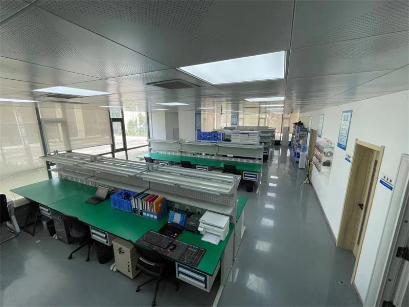
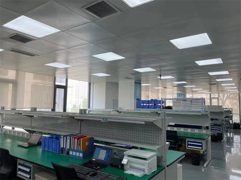
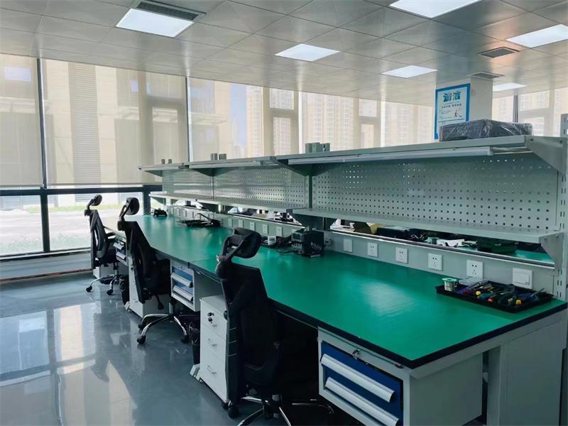
Factory Environment

Cinofiber will continue to be a leader in the optical communication industry, providing customers around the world with more stable, reliable, and high-quality products and services.
Certificate Of Honor

Related Products

S-S8180 Single-Frequency Anti-jamming &Anti-spoofing Antenna

S-S8180 Single-Frequency Anti-jamming &Anti-spoofing Antenna Confirmation FormSerialNumberprojectindex1Number of array elements8-lement2size180×180×25.5mm (±0.5mm)3weight≤890g4frequencyB1/E1/L15Anti-interference performance≥115dB (single jamming)≥105dB (three jamming )≥90dB (seven jamming )6Power supply voltageDC 12~36V7interface1x J30J-9ZK, 1xSMA8Power consumption≤17W9Structural installation accessories16 M3×8 screws and 4 mounting bracketsApplication Parameter Confirmation FormSerialcontentdefault valueCustomer confirmationN b1Structural installationStructural installation method1)Overhead installationThe antenna body shall be mounted to the platform using the provided mounting brackets. A minimum clearance of 10mm shall be maintained beneath theantenna to ensure adequate airflow and heat dissipation.2) Face to face installationThe antenna shall be mounted with itsbottom surface in direct and full contact with a metal surface to maximize thermal conduction and heat dissipation.Default: Overhead installation.If overhead installation cannot beachieved, please inform us in advance so that we can discuss and determine an alternative solution.□ Accept Default □ Customize: ______2connect1. Confirm whether a digital or radio frequency (RF) connection is used;2. Confirm the power supply method and power supply capacity;3. If using a digital connection, confirm the serial port output level;4.Confirm the output level of the anti- interference serial port5.Confirm the power supply connection method;6.Confirm the serial port connection method.1. Both connection methods aresupported, and the customer must confirm and select. Differentconnection methods correspond to different parameter configurations.2. Power supply method and capacity: The default power supply uses anXT30U-M male connector, and the power supply capacity must meet the device's peak power consumption of 26W.3. For digital connections, the default receiver serial port output level isLVTTL_3.3V. RS232 is available as options.4. The default anti-interference serial port output level is LVTTL_3.3V.RS232 is available as an option.5. A J30J connection cable isprovided by default, and the power supply uses an XT30U-M maleconnector. The customer needs to provide the corresponding female connector for mating.6. A J30J connection cable isprovided by default, and the serial port uses a DuPont male pin connector.□ Digital Connection□ RF ConnectionPower Supply: __________Power Supply Capacity: □ Meets SerialReceiver serial Port Level:□ Accepts Default□ Customizes: ___________Anti-interference serial Port Level:□ Accepts Default□ Customizes: ___________Power Connection: __________Serial Port Connection: __________3Output ProtocolIf using a digital connection, please confirm the following built-in receiver configurations:1. Output protocol: UBX or NMEA0183;2. Baud rate: 115200 or 230400 or other;3. Output frequency: 5Hz.d dThe default built-in receiverconfiguration for the single-frequency anti-jamming antenna is as follows:1. Output protocol: UBX protocol;2. Baud rate: 115200;3. Output frequency: 5Hz.□ Accept Default □ Customize: ______4Output Protocol(anti-jamming )Interference Monitoring Configuration: Output Protocol: ZSAJ ProtocolBaud Rate: 115200, 230400, or other (customizable upon request)Default configuration:Output Protocol: ZSAJ ProtocolBaud Rate: 115200□ Accept Default□ Customize: ______5End useThe product is limited to civilian unmanned platforms and high-precision positioning scenarios, including but not limited to drones, unmanned ships, autonomous vehicles, marine operations, and surveying and mapping.End use: ______6Application PlatformMulti-rotor drones, fixed-wing drones, unmanned surface vessels, autonomous vehicles, ground base stations, etc.Application platform: ______7Main applicationscenariosAerial surveying, inspection and patrol, logistics and distribution, precisionagriculture, offshore operations, communication relay, scientific research, etc.Application scenario: ______8End-usecountry/region:Country and region: ______Important Note: The above confirmation is the basis for product delivery. Once confirmed, any subsequent changes may incur additional costs or affect the deliverydate. If the default configuration cannot meet your application requirements, please provide detailed specifications in the "Customization" section. mplementation is only permitted after mutual communication and confirmation. Unless otherwise specified, electrical connection accessories (connectors, cables, etc.) will be based on the default configuration.Confirmation signature:Confirmation Date

S-S4100 Single-Frequency Anti-jamming &Anti-spoofing Antenna

S-S4100 Single-Frequency Anti-jamming &Anti-spoofing AntennaSerialNumberprojectindex1Number of array elements4 Array Elements2size100× 100×24.9mm (±0.5mm)3weight≤310g4frequencyB1/E1/L15Anti-interference performance≥115dB (single jamming)≥100dB (three jamming )6Power supply voltageDC 12~36V7interface1xJ30J-9ZK , 1xSMA8Power consumption≤10W9Structural installation accessories8 M3 ×8 screws and 4 hax studsApplication Parameter Confirmation FormSerialNumbcontentdefault valuer1Structural installationStructural installation method:1.Overhead installationUse hex studs to mount the antennabody to the platform, ensuring aminimum clearance of 10 mm beneath the antenna for proper airflow and heat dissipation.2. Fact to face installationMount the antenna with its bottomsurface in close contact with a metal mounting surface for effective heat conduction.Default: Overhead installation.If overhead installation cannot beachieved, please inform us in advance so that we can discuss and determine an alternative solution.2connect1.Confirm whether a digital or radio frequency (RF) connection is used;2.Confirm the power supply method and power supply capacity;3.If using a digital connection, confirm the serial port output level;4.Confirm the output level of the anti- interference serial port5.Confirm the power supply connection method;6.Confirm the serial port connection method.1. Both connection methods aresupported, and the customer must confirm and select. Differentconnection methods correspond to different parameter configurations.2. Power supply method and capacity: The default power supply uses anXT30U-M male connector, and the power supply capacity must meet the device's peak power consumption of 15W.3. For digital connections, the default receiver serial port output level isLVTTL_3.3V. S232 is available as options.4. The default anti-interference serial port output level is LVTTL_3.3V.RS232 is available as an option.5. A J30J connection cable isprovided by default, and the power supply uses an XT30U-M maleconnector. The customer needs to provide the corresponding female connector for mating.6. A J30J connection cable isprovided by default, and the serial port uses a DuPont male pin connector.3Output Protocol (Receiver)If using a digital connection, please confirm the following built-in receiver configurations:1. Output protocol: UBX or NMEA0183;2. Baud rate: 115200 or 230400 or other;3. Output frequency: 5Hz.d dThe default built-in receiver configuration is as follows:1. Output protocol: UBX protocol;2. Baud rate: 115200;3. Output frequency: 5Hz.4Output Protocol (anti-jamming )Interference Monitoring Configuration: Output Protocol: ZSAJ ProtocolBaud Rate: 115200, 230400, or other (customizable upon request)Default configuration:Output Protocol: ZSAJ ProtocolBaud Rate: 1152005End useThe product is limited to civilian unmanned platforms and high-precision positioning scenarios, including but not limited to drones, unmanned ships, autonomous vehicles, marine operations, and surveying and mapping.6Application PlatformMulti-rotor drones, fixed-wing drones, unmanned surface vessels, autonomous vehicles, ground base stations, etc.7Main application scenariosAerial surveying, inspection and patrol, logistics and distribution, precisionagriculture, offshore operations, communication relay, scientific research, etc.8End-usecountry/region:Important Note: The above confirmation is the basis for product delivery. Once confirmed, any subsequent changes date. If the default configuration cannot meet your application requirements, please provide detailed specifications only permitted after mutual communication and confirmation. Unless otherwise specified, electrical connection acc the default configuration.Confirmation signature:Confirmation DateConfirmation FormCustomer confirmation□ Accept Default □ Customize: ______□ Digital Connection□ RF ConnectionPower Supply: ___________Power Supply Capacity: □ Meets SerialReceiver serial Port Level:□ Accepts Default□ Customizes: ____________Anti-interference serial Port Level:□ Accepts Default□ Customizes: ____________Power Connection: ___________Serial Port Connection: ___________□ Accept Default□ Customize: ______□ Accept Default□ Customize: ______End use: ______Application platform: ______Application scenario: ______Country and region: ______s may incur additional costs or affect the deliverys in the "Customization" section. mplementation iscessories (connectors, cables, etc.) will be based on

JDJ-7 7-frequency probe and strike integrated square array

7-frequency integrated exploration and drilling system in a square formation + small spherical probe for detection/positioningFixed-type-Large spherical detectorFixed type-detects small spherical ballsVehicular-type detection of large spheresVehicular-type detection small sphereProduct Description:The 7-frequency integrated detection and countermeasure quad阵 device system consists of a detector and a four-directional directional jamming array, capable of detecting, identifying, and interfering with or countering drones. It enables drones to hover in place, make forced landings, or return, effectively safeguarding low-altitude airspace security and preventing drone entry into designated zones. Featuring outstanding detection and defense capabilities along with long-range operational performance, the system requires no personnel presence and can automatically conduct drone detection and defense operations. It can be deployed either fixedly or on vehicles according to specific scenario requirements, and may optionally include direction-finding functionality.characteristic :Omnidirectional emission: A four-directional jamming device provides 360° omnidirectional interference coverage.Network Management: Multiple systems can be centrally managed via a LAN/Internet.Unattended operation: The software backend allows setting automatic processing policies, enabling 24/7 unmanned operation.Product Parameter : Parameter Nameparameter valuesoverall unitOverall dimensions of the machine700 × 700 × 445 mm (excluding tripod and vehicle mount base)Total weight of the machine26kgDeployment MethodFixed-type, Vehicle-mounted typepower supply modemains power AC 220VTotal machine currentTargeted protection case: 120A (full-load operation)  working temperature-20~50℃Detection Section  Detection Frequency400MHz,600MHz,800MHz900MHz,1.1GHz,1.2GHz,1.4GHz,1.5GHz,2.4GHz,5.8GHzDetection Angle360° omnidirectionalDetection Precision±100Impact SectionHit Frequency800M、900M、1.2G、1.6G、2.4G、5.2G、5.8GImpact Power800M、900M、1.2G、1.6G、2.4G、5.2G、5.8G  AngulationHorizontal: 65°, Vertical: 30° (orientated)Functional ProtectionTemperature control protection, reflection protection

Handheld detectors and locators support custom scanning in the frequency range of 100MHz-6200MHz

PRODUCT SPECIFICATIONPerformance IndicatorsDetection Bands (Customizable)Supports custom scanning from 100MHz to 6200MHzDetection Distance1.5–2 km (urban environment) 2–3 km (open environment)Operational principleSpectrum identification, Drone ID identification, Remote ID identificationResponse time≤6sDetection recordMore than 10 itemsBoot time≤30sPhysical IndicatorsScreen size6 inchesDuration of flight3–4 hours, supports charging while usingLevels of protectionIP65Working temperature-25℃~+40℃Weight of equipment≤650gJD2-HDevice size≤ Dimensions: 178mm × 85mm × 35mm (excluding antenna and accessories). Antenna specifications: 2 units, each with a diameter of Φ20mm and length of 170mm.Passive handheld radio detector using spectrum, DJI ID & Remote ID. Covers 100MHz–6200MHz for real‑time drone signal analysis, identification, alerting & tracking. Features map UI, Bluetooth/4G for alerts/logs & database updates. No radiation, one‑hand operation, portable. Ideal for public security, drone cases & command coordination.Full-band coverage: 100MHz–6200MHz custom scan.Multi-model recognition: 800+ models (DJI, Autel, Hubsan, Xiaomi, etc.), supports FHSS & wall-penetrating drones.Whitelist/Blacklist: One‑click mark, whitelisted drones no alert.Drone & pilot positioning: Supports DJI mainstream & RID‑cooperative drones.Multi‑target tracking: ≥10 drones, detection, positioning & tracking.Device networking: Backend connection, alert reporting.Auto library building: Expandable spectrum library, manual/auto learning & adding.PTT intercom: Wireless group intercom for real‑time coordination.Product Features

Online Inquiry

We will contact you within one working day. Please pay attention to your email.

%{tishi_zhanwei}%